By Eugenio Galbán
Electrical Current Effects on bearings
Bearings are a crucial part of any mechanical power transmission system. Their capacity to transmit power with the minimum energy loss makes bearings a critical element that needs to be under special analysis in terms of potential sources of damage to the overall machine. The bearing’s basic components are an inner ring, outer ring, and rolling elements, being rollers or balls. Materials used in these components are steel or ceramics.
In applications where electricity is present, for example in generators applications, it is necessary to ensure the right insulation of the bearings, in this case generators ground connection through brushes, can fail due to wear in the contact area, this will induce electrical energy to flow through bearings. Electricity will pass through where less resistance is found. With lesser resistance, the temperature rises proportionally to the current intensity “I” amount flowing through the parts in contact. From Ohm’s Law [2] it can be induced that at a certain voltage value “V” when resistance “R” is zero, the current intensity “I” tends to infinity.
The classification of damages in bearings related to electrical charges as Electrical Erosion, and it subdivides this classification into two types of failures, Excessive Voltage, and Current Leakage. [1]
If the bearing components are exposed to electrical charges, now when the lubricant film is not sufficient, the rolling elements can be in direct contact with the rings raceways and a short circuit will appear, provoking extremely high current intensity at the contact points, this will lead to a rise in temperature above the material melting point and welding the points in contact. [4]
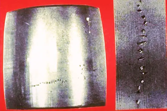
Figure 1. Excessive Voltage crater damage on roller and inner Ring raceway. [9]
When the bearings are under operation, the rolling motion and heavy loads will cause the welded points by electrical charges to be detached from the surface leaving craters on the rolling surface. This phenomenon is due to an embrittlement of the surrounding material of the welded points because of the high-temperature rise during the electrical arc is taking place. This is caused by the Excessive Voltage failure type. [3]
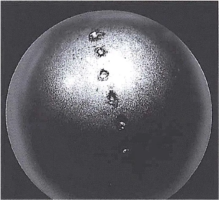
Figure 2. Excessive Voltage crater damage on ball. [12]
The damage in bearings due to electricity can be evaluated by the visual analysis of the rolling elements and the rings’ raceways.
The rolling elements can show signs of electrical damage by their color when diagnosed, as shown in Figure 3.
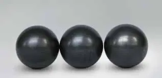
Figure 3. Electrical corrosion has a dark color that covers the entire ball surface [8]
Another type of damage diagnosis related to electricity in bearings is shown in Figure 4, when the rolling surfaces shows a uniformly distributed fluting-craters appearance along the rolling surface [7]. This phenomenon occurs when the current intensity is relatively low, but it is applied for a long period of time. This is classified as Current Leakage or Washboarding.
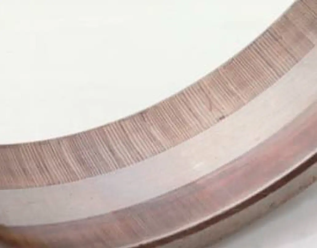
Figure 4. Current Leakage or Washboarding damage. [13]
The effect on bearings, besides the physical visible marks, is also seen by the degradation of the lubricant because of the high temperature rise. Grease or oil will be damaged and will no longer be capable of performing properly as intended. The chemicals used will decompose in other substances with temperature, substances which will no longer perform the right lubrication properties, starting to be contaminated.
The most critical periods of time are the ones where the lubricant film is not able to form, being the starting period and the stopping period. The lubricant is chosen to form the lubricant film with a determined operational speed and load in the application. When the lubricant film fails to form, the metal-to-metal contact takes place.
In addition, the particles detached from the rolling surfaces, will be solid contamination that will indent the rings raceways gradually, starting spalling on the surfaces over time. Figure 5 shows indentations occurred due to hard particles and Figure 6 shows the damage that can occur when indentation by hard solid contaminants evolve into detached material damage on the rolling surfaces.
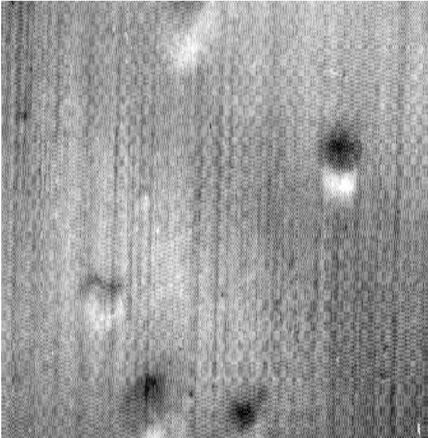
Figure 5. Indentations on raceway by hard particles. [12].
The damage can be detected by high levels of noise, vibrations, and temperatures under operation.
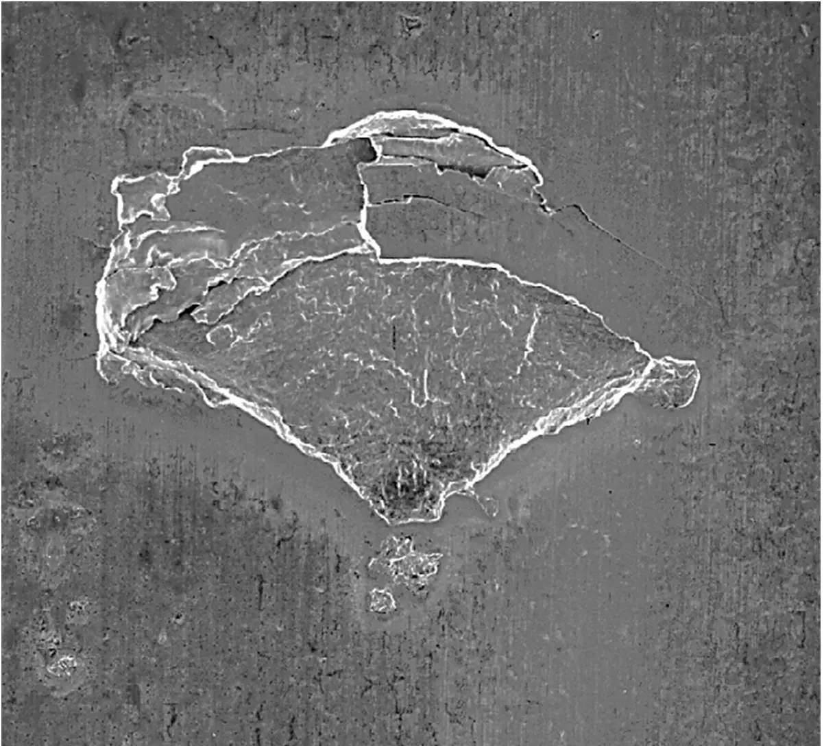
Figure 6. Detached material from Indentations by hard particles.
Application example
A wind turbine generator Drive end and non-Drive end bearings have been failing repeatedly, forcing technicians to replace them before their expected lifetime. The generator shaft uses steel bearings 6338 M/C3VQ658. Figure 7 and Figure 8 show the schematic view of the Generator Assembly and the Bearing Assembly.
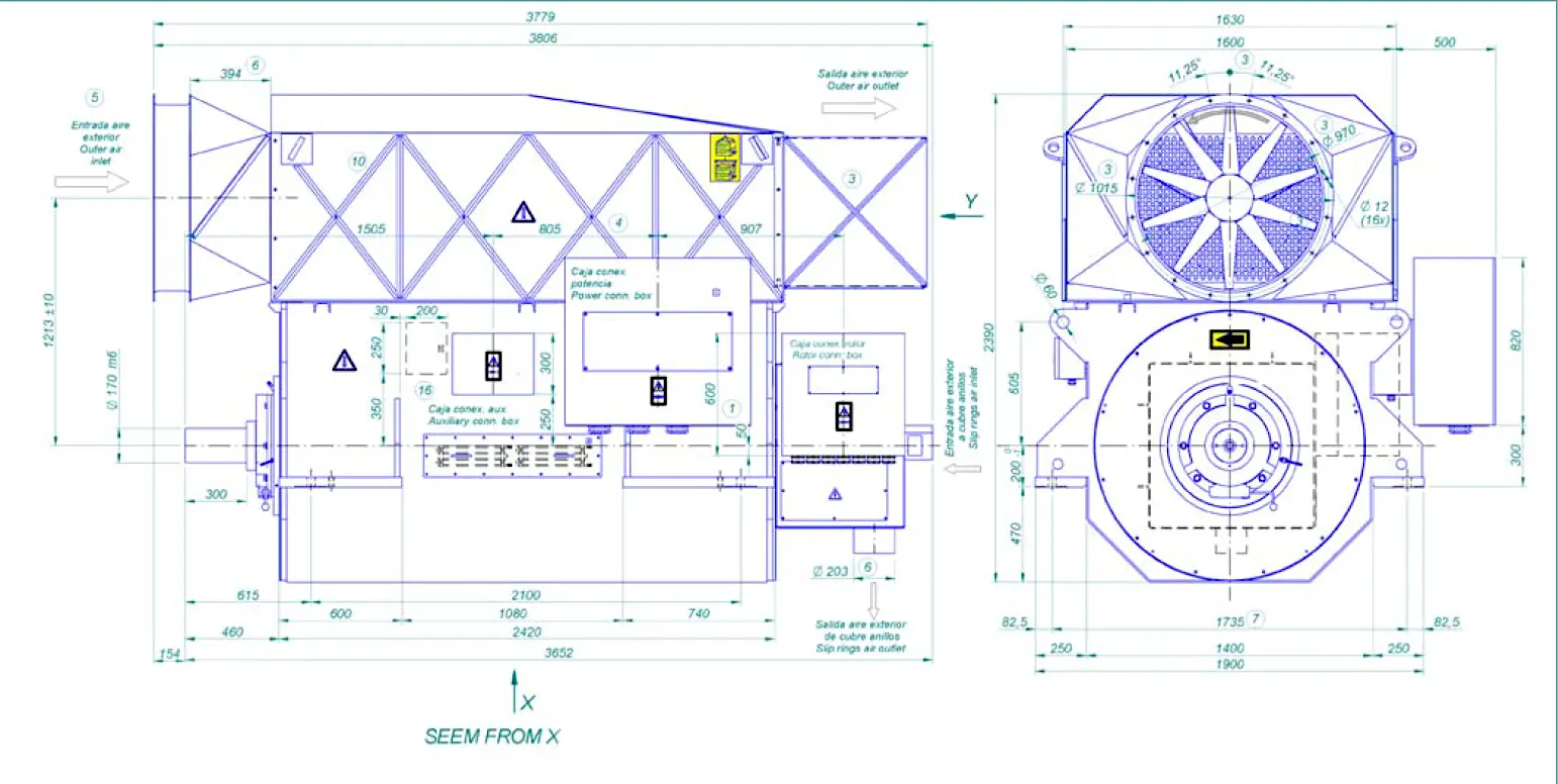
Figure 7. Example Generator assembly drawing
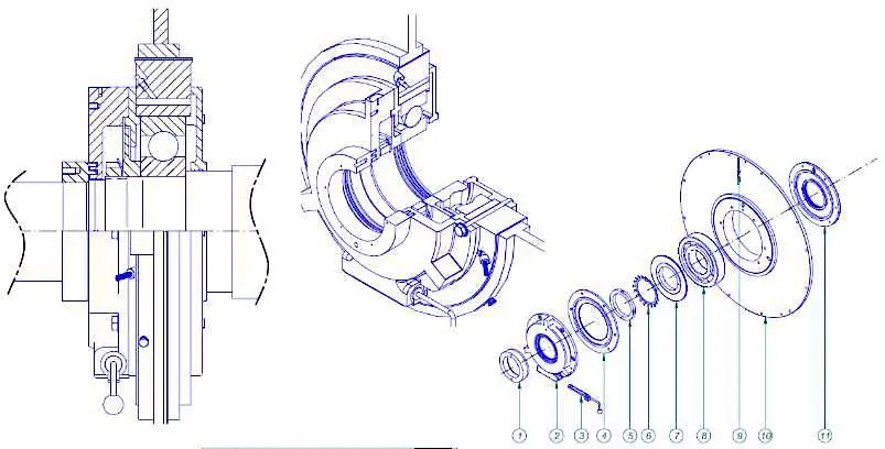
Figure 8. Bearing assembly view for the example
The bearing technical information is as follows:
| d [mm] | 190 |
| D [mm] | 400 |
| B [mm] | 78 |
| C [kN] | 371 |
| Co [kN] | 430 |
| M [kg] | 47.5 |
In the following images it can be seen an assembly drawing of the generator and the bearing component general view.
At the time of the external inspection the bearings were received, and components were separated and the rings raceways and rolling elements were inspected thoroughly. Figure 9 shows the disassembled bearings at ABS facilities ready for inspection. Figure 10 shows the inner ring surface quality inspection of the received bearings.
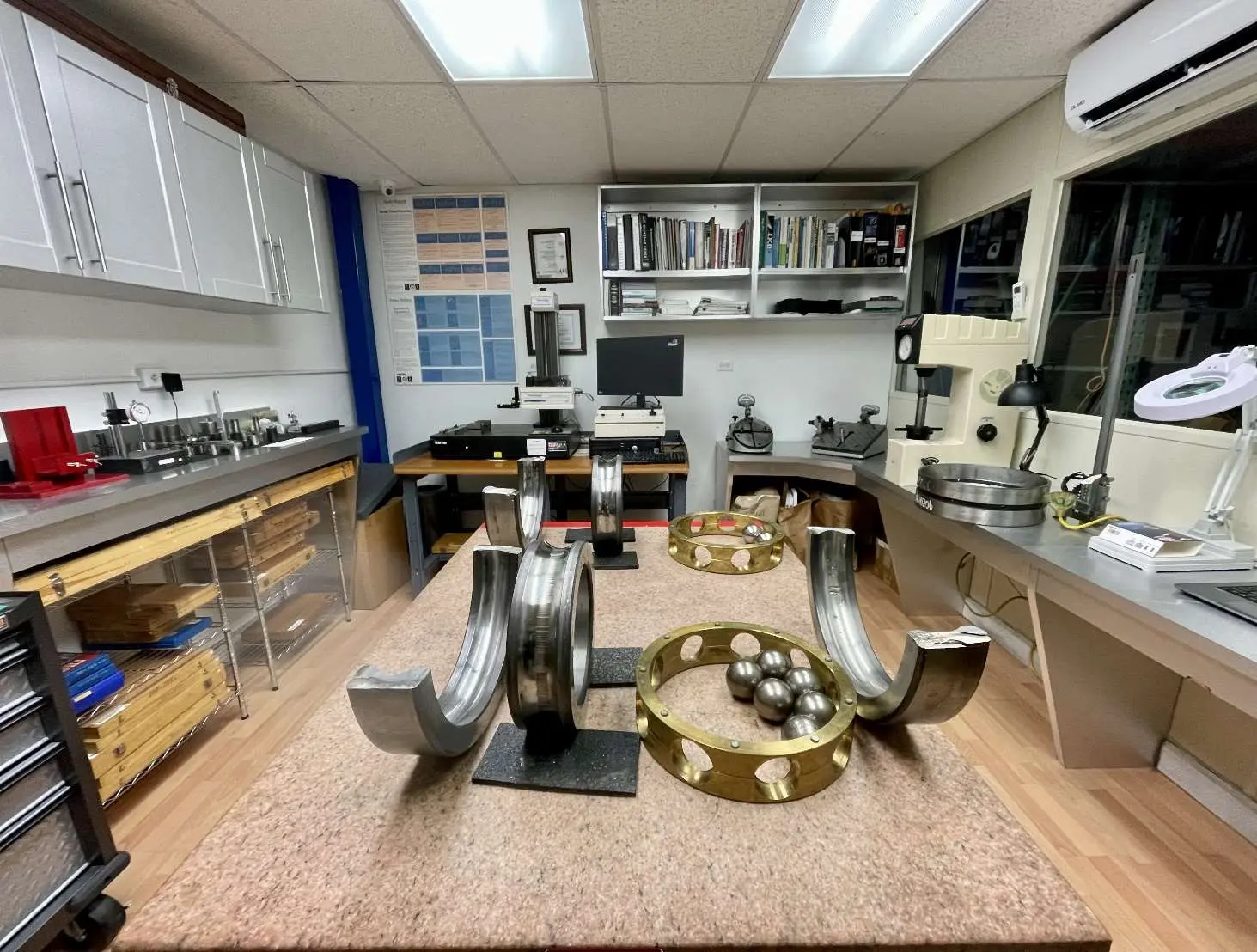
Figure 9. View of bearings disassembled for inspection.
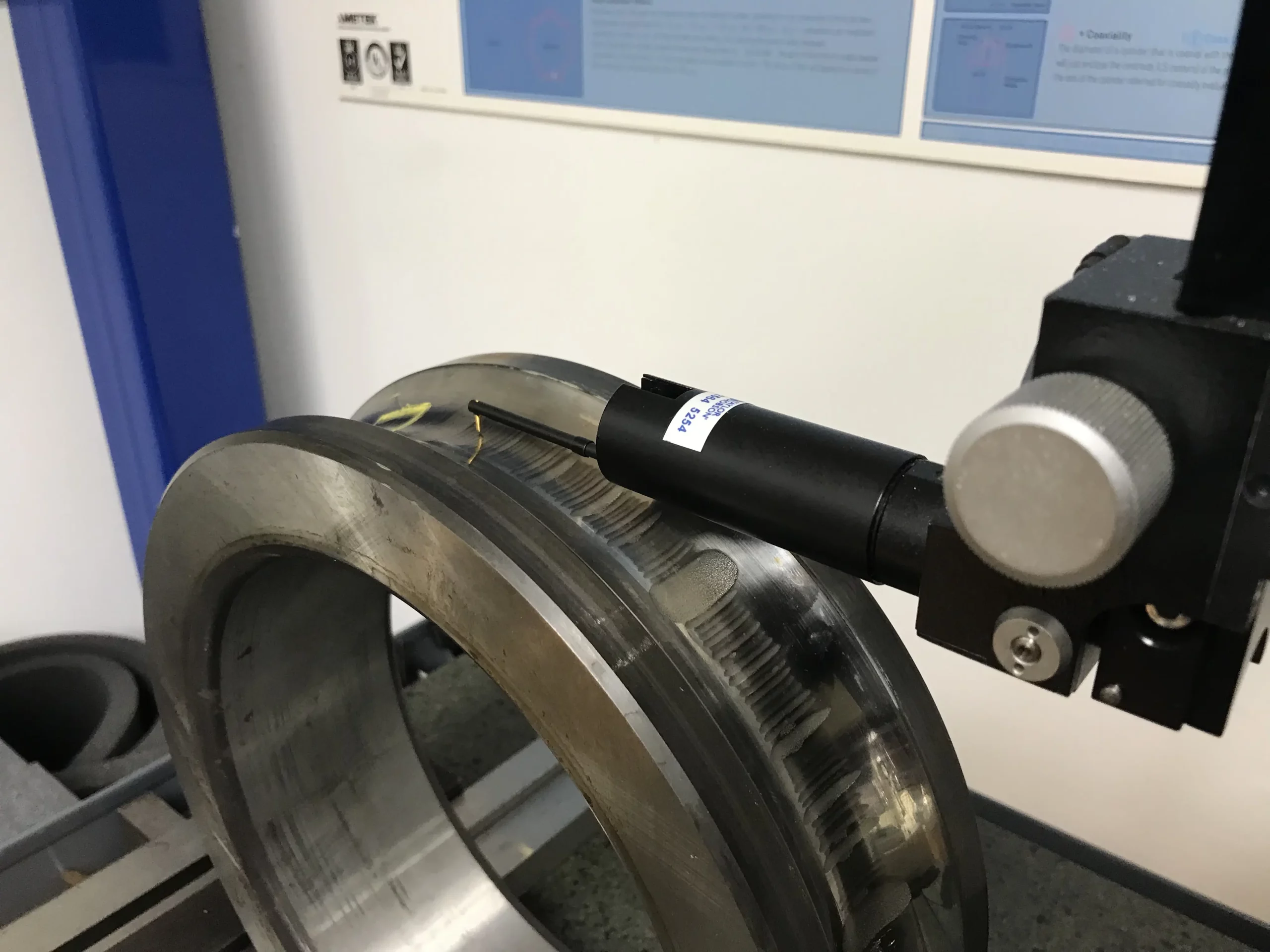
Figure 9. View of bearings disassembled for inspection.
At the time of the external inspection the bearings were received, and components were separated and the rings raceways and rolling elements were inspected thoroughly.
The damaged bearings were classified for both sides as C4, I8 and D8.
Findings:
1- The Bearing C4 inner ring, drive end side, the raceway showed axial groove marks distributed uniformly along the rolling surface.
This type of failure is diagnosed as Electrical Fluting. Bearings have been subjected to stray electrical current leakage over time due to parasitic electrical currents from the stator having electrolytic corrosion. This failure is known as Current Leakage. [3]
This type of damage will provoke high levels of vibration, noise, spalling and the base lubricant oil to burn and harden, causing poor lubrication condition.
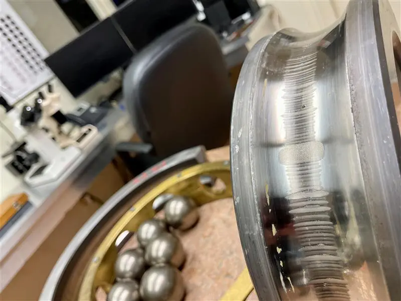
Figure 11. Bearing C4 inner ring with Current Leakage damage.
2- Bearing C4 outer ring raceway, drive end side, shows axial grooves and micro-pitting marks due to the electrical erosion damage, shown in Figure 12, 13 and 14.
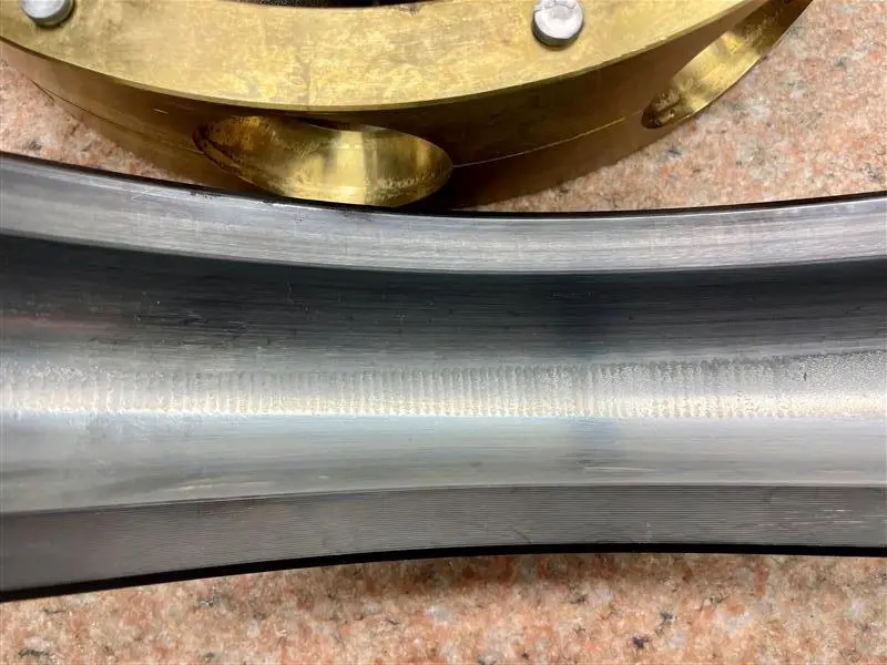
Figure 12. Bearing C4 outer ring with Current Leakage damage.
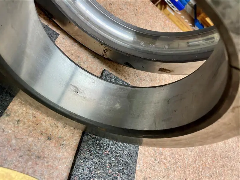
Figure 13. Bearing C4 with Current Leakage and Excessive Voltage cratering damage.
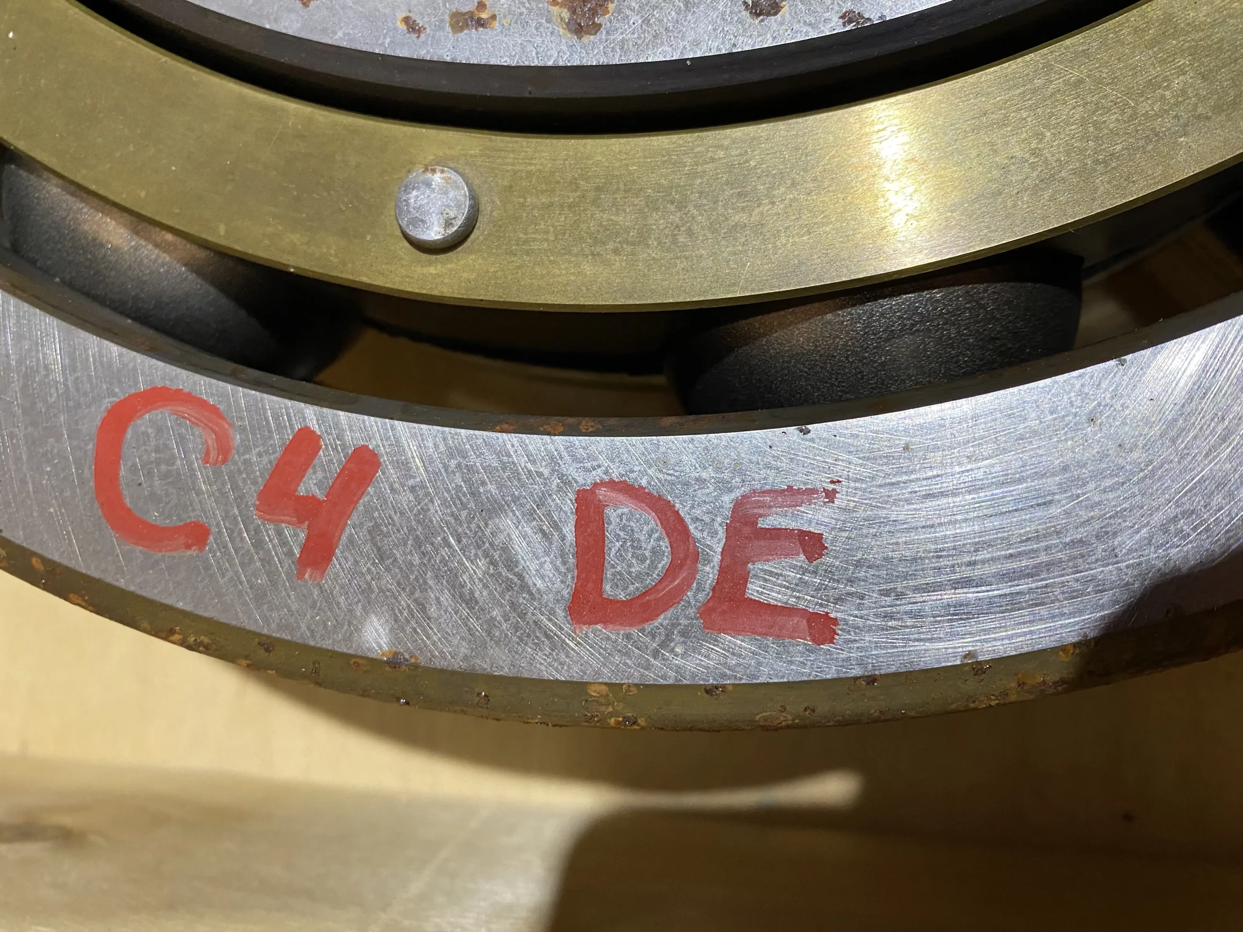
Figure 14-1. Bearing C4 with Electrical Erosion.
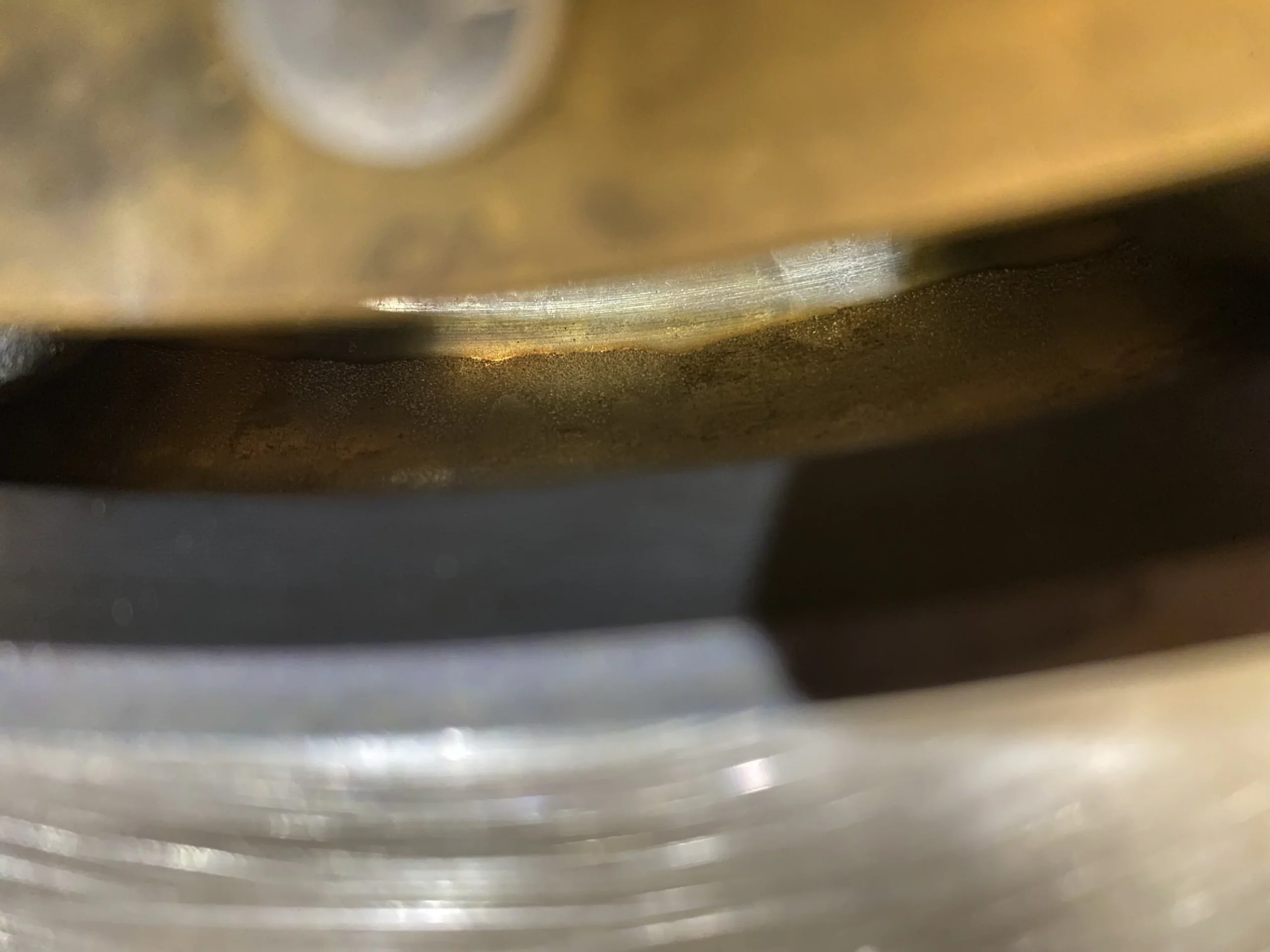
Figure 14-2. Bearing C4 with Electrical Erosion.
The bearing has been subjected to stray electrical current leakage over time due to parasitic electrical currents from the stator having electrolytic corrosion. This failure is known as Current Leakage. [3]
In addition, micro-pitting can be seen, what is known as Excessive Voltage as the electrical corrosion takes place.
Consequences are like the previous finding.
Bearing I8 outer ring raceway, drive end side, shows axial grooves and micro-cratering marks due to the electrical erosion damage, shown in Figures 15 and 16.
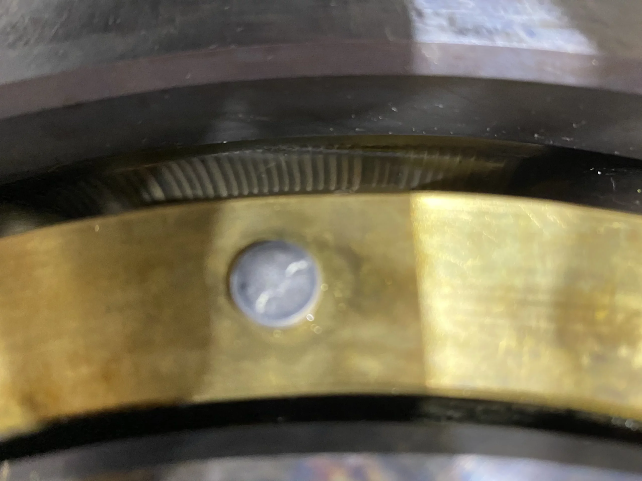
Figure 15. Bearing I8 with Current Leakage damage.
The damage of this bearing is like the damages found in the C4 bearing outer ring.
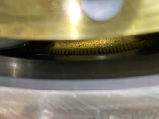
Figure 16. Bearing I8 with Electrical Erosion damage
4- Bearing D8 inner ring raceway, drive end side, shows axial grooves and micro-pitting marks due to the electrical erosion damage, shown in Figure 17 and 18.
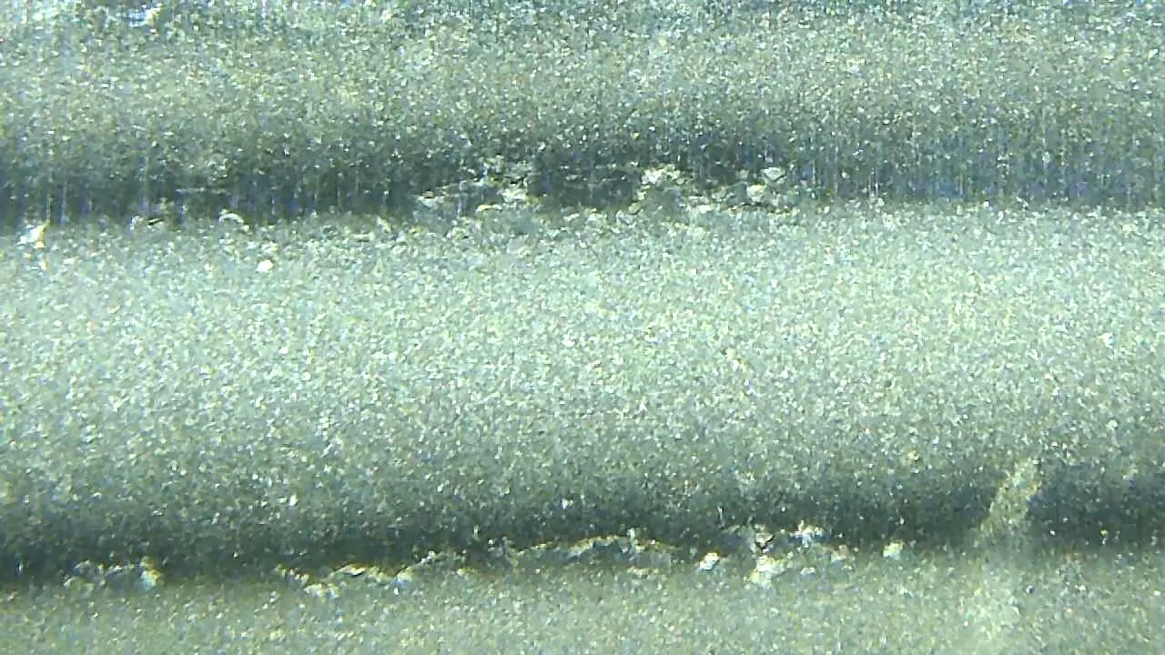
Figure 17. Bearing D8 inner ring raceway augmented view with Current Leakage and cratering damage.
Amplified images of the raceway and the rolling elements are shown as follows:
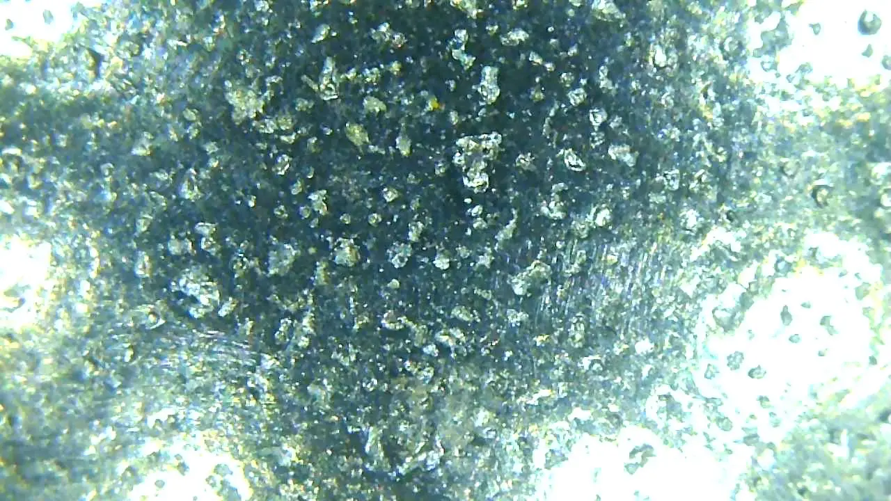
Figure 18. Bearing D8 ball augmented view with cratering damage.
From these images the electrical damage can be seen. The micro-cratering of the rolling elements shows a distinctive mark of Excessive Voltage.
The marks shown in the inner ring raceway of this bearing, is showing the Excessive Voltage damage as well as Current Leakage damage in a combined form.
The analysis of the raceway using a Taylor-Hobson profilometer as shown in figure 10, illustrate the damage occurred, the bearing cannot operate under this condition. The inner ring rolling surface is severely damaged as results in Figure 19 are showing.
Scenarios where the brushes are unable to evacuate all generated parasitic current: brushes are installed incorrectly, damaged, worn, presence of contaminated grease, insufficient spring pressure.
Experience has shown that the best solution is to replace the bearing for a hybrid bearing which provide perfect insulation between rotor and stator, avoiding circulation of all types of current. Manufacturers are aware of this occurrence which is why newer generations come equipped with hybrid bearings.
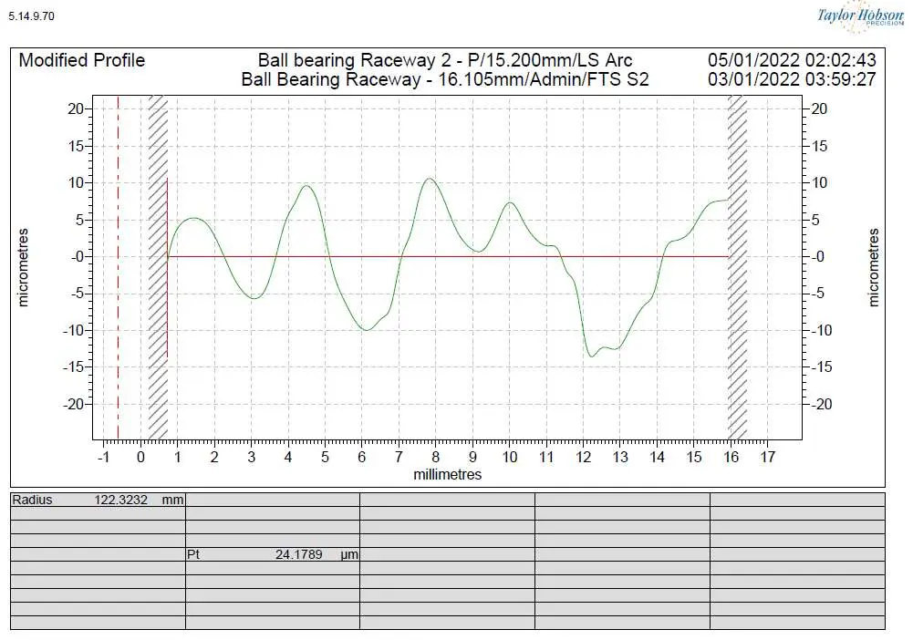
Figure 19. Bearing D8 inner ring raceway profilometer result.
Solutions to prevent Bearings Electrical Erosion Damage
Substitute bearings with potential electrical damage sources with coated surfaces, complete ceramic bearings or hybrid bearings are the possible approaches to avoid this type of failure. [7]
Considering DC electrical currents, the coating used acts as a pure ohmic resistor, therefore material and coating thickness used are critical to analyze at the time of choosing the right insulation design. In an ohmic resistance connection, the voltage is proportional to the current intensity according to Ohm’s Law. [10]
When considering Alternating Currents insulators, it is necessary to analyze the effect of its impedance, since these currents act like a resistor and a capacitor parallel connection as shown in Figure 20. [10]
![Figure 20: Parallel connection of resistor and capacitor. (a): circuit symbol, (b): locus* of the complex conductance, (c): current-voltage phasor diagram. [2]](https://www.atlantic-bearing.com/wp-content/uploads/2022/06/Fig-20.webp)
Figure 20: Parallel connection of resistor and capacitor. (a): circuit symbol, (b): locus* of the complex conductance, (c): current-voltage phasor diagram. [2]
*Locus: Represents the dependence of a complex quantity on the frequency in the complex plane.
The impedance depends on the capacitance, current intensity frequency and in the electrical resistance of the coating layer.
The Capacitance “C” of an arrangement of conductors, is a scalar quantity specifying the quantity of electric charge that may be stored by this arrangement for a given voltage “V” between the conductors. [2]
The current admittance in a parallel connection of a resistor and capacitor is given by the Equation 1 [2]:
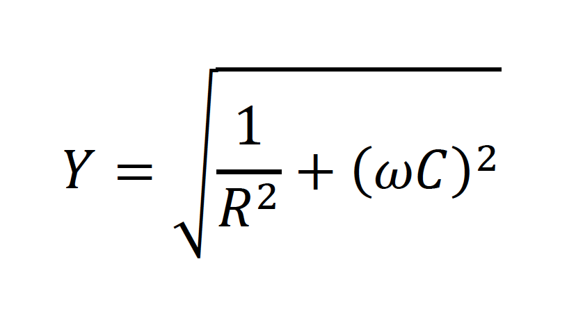
Equation 1
Since impedance is the reciprocal of the admittance as shown in Equation 2 [2]:
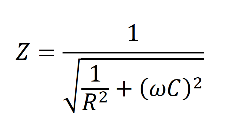
Equation 2
And the capacitance of a plate capacitor is given by Equation 4:
Where:
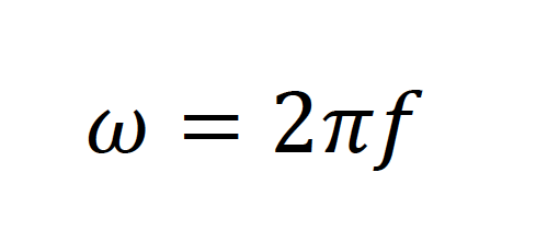
Equation 3
And the capacitance of a plate capacitor is given by Equation 4:
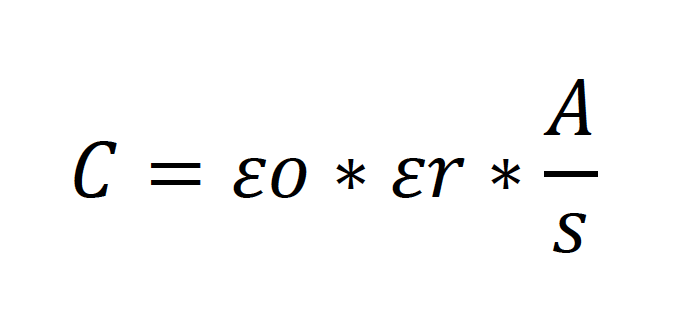
Equation 4
Where:
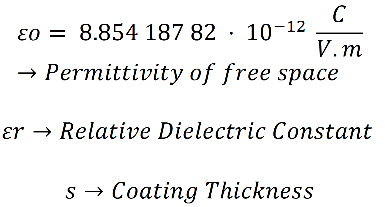
The Permittivity of free space ε0, is a proportionality factor between the displacement and the field strength in a vacuum at any position in a uniform or non-uniform field. [2]
The Relative Permittivity or Relative Dielectric Constant εr, is a nondimensional material-dependent quantity that specifies the decrease of the electric field strength when a material (dielectric) is placed in an electric field. [2]
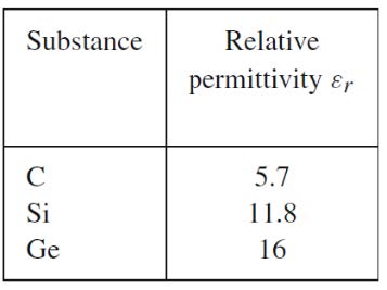
Some examples for εr are given in the Table 1:
Table 1: Relative Dielectric Constant εr values for some substances [2]
Coated bearings are used with inner ring bore surface and/or outer ring outer surface coated with a ceramic material. Since in presence of AC the current intensity frequencies are the most critical parameter to consider, it is necessary to achieve the maximum impedance as possible.
The variables that have influence in the impedance are coated thickness layer, coated area, and the Relative Permittivity. To achieve maximum protection, it is advisable to coat the inner ring bore since the area is minimum, having a coated thickness properly selected.
Materials used are mainly Aluminum Oxide (Al2O3) with additional specific additives that increase wear and corrosion resistance. [10]
This solution has the disadvantage that with high frequencies, electrical current may pass through, especially when frequency-converters are used. [10]
In addition, if the coated surfaces suffer scratches by micro movements or during mounting, this will allow electricity to flow through the surfaces in contact and damage the bearing.
Hybrid bearing on the other hand has the advantage to fully isolate the bearings by using completely ceramic rolling elements. Materials mainly used are Silicon Nitride (Si3N4) or Zirconium Oxide (ZrO2). [11]
References
- ISO 15243, “Rolling bearings — Damage and failures — Terms, characteristics and causes”.
- Springer, Walter Benenson, John W. Harris, Horst Stöcker, Holger Lutz, “Handbook of Physics”.
- NREL, T.E Tallian, Global Energy Concepts LLC, Kirkland, Washington, “Failure Atlas for Rolling Bearings in Wind Turbines”, 2006.
- SKF, Bearing Damage and Failure Analysis, Pub BU/I3 14219/2 EN, June 2017.
- INA/FAG, FAG Australia Pty Ltd, Rolling Bearing Failure Analysis, 2005.
- Schaeffler/FAG, Rolling Bearing Damage-Recognition of damage and bearing inspection, Publ. No. WL 82 102/2 EA.
- Koyo Seiko Co. Ltd, CAT. No. 322E, “Rolling Bearings: Failures, Causes and Countermeasures.
- NSK, Bearing Doctor-Bearing Maintenance Guide, Rev 2/AC/1M16, 2016.
- Belgrade University, Kragujevac University. Aleksandar Vencl, Vlada Gašić and Blaža Stojanović. Conf. Series: Materials Science and Engineering 174 (2017). “Fault tree analysis of most common rolling bearing tribological failures”.
- SKF, “A solution to increase reliability and machine uptime”, PUB BU/P2 17344 EN · May 2017.
- Schaeffler, “Materials for Rolling Bearing Technology”, TPI 226 GB-D
- American Bearing Manufacturers Association, “Advanced concepts of Bearing Technology – Bearing Life and ISO Damage Classification”, Oak Brook, IL-June 2018.
- Schaeffler/FAG, Rolling Bearing Damage – Symptoms, Causes, Remedies, Publ. No. WC Damages / EN-GB / 201107.25.
Eugenio Galbán
 Eugenio Galbán joined Atlantic Bearing Services (ABS) in 2018 as a Mechanical Engineer Team Leader in their facilities located in China, focused on designing, manufacture and quality assurance good practices for ABS products.
In addition, while this time, he has been involved in several international projects related to mechanical power transmission elements with multidisciplinary teams of mechanical engineers, contributing to failures analysis and engineering solutions to significantly improve the life expectancy of components in the field. He has worked serving to wind industry applications, steel mill applications, cement industry applications and others. Eugenio is a member of the American Bearing Manufacturer Association (ABMA) as well as an American Gear Manufacturers Association (AGMA).