By José Martínez-Escanaverino
Download Rail Transportation of Wind Turbine Main Shaft Assembly in pdf format.
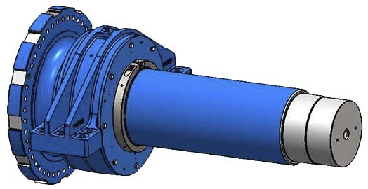
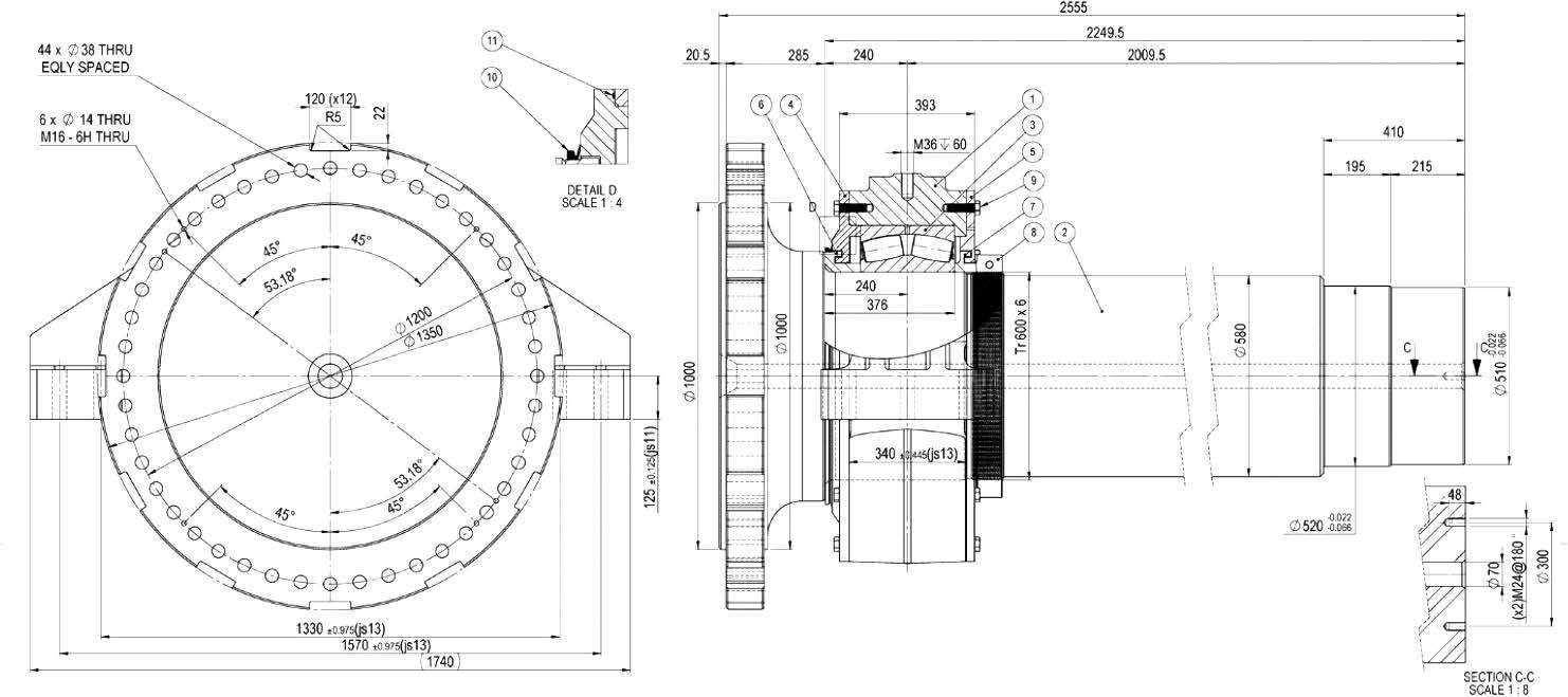
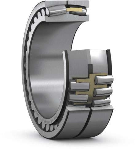
Many Wind Turbines have a main shaft assembly, consisting of the main shaft, rolling bearing, and housing attached, Figure 1. The principal dimensions of the main shaft assembly are given by the general drawing in Figure 2, and a cut-away view of the rolling bearing is shown in Figure 3.
A number of these main shaft assemblies arrive by ship to the United States, and they are sent to their destination in railroad cars. As is well known, rail transport is the usual means of transportation for heavy and bulky cargo, but in this case, some concerns arise about the damage that rail transport may have inflicted on the rolling bearing. According to certain criteria, such damage does not occur during truck transportation.
The purpose of this article is to analyze the shocks involved in truck and rail transportation in the United States and compare them with the shock strength of the main shaft rolling bearings, in order to clarify the real possibilities of damage during the above-mentioned transportation.
Vibration and Shocks During Truck and Rail Transportation
The Sandia National Laboratories (SNL), managed and operated by the National Technology and Engineering Solutions of Sandia, is one of three United States National Nuclear Security Administration (U.S.NRC) research and development laboratories.
Located in Albuquerque, New Mexico, and Livermore, California, the SNL has been involved since 1970 in the study of the shock and vibration environments of truck and rail transportation of nuclear fuel shipping casks, with the aim of assuring its safety.
The dynamic environments of cargo under land transportation are a mixture of vibration, occasional shock superimposed on the vibration, and isolated shock which occurs in single events.
Vibration is the excitation that occurs whenever the carrier is in motion and is produced when the carrier suspension system and carrier frame members react to surface irregularities in highways or railroads under the effects of the carrier motive system. Conventionally, the acceleration of the carrier due to vibration is limited to a maximum of 2 g, and usually envelopes 99 % of all acceleration measurements.
Superimposed shock produces a cargo motion response stronger than 2 g, and envelopes about 1% of all acceleration measurements. These shocks consist of decaying transient pulses superposed and intermixed with vibration. For trucks, superimposed shocks appear when crossing bridge approaches, railroad tracks, and by striking potholes. For rail cars, superimposed shocks are produced by run-in, run- out and by crossing bridges, switches, and other track intersections.
Isolated shocks occur during car coupling operations. These shocks are significantly more severe than the superimposed ones; however, they occur only during train formation, which is a less frequent event. In trucks moving normally on highways, no similar isolated strong shocks happen.
The work of J.T. Foley and M.B. Gens, published in 1971, opened this research front [1], including data obtained from sources back since 1960. Afterward, a group of reports by teams headed by C.F. Magnuson were published during the period 1977/1982 [2, 3, 4, 5, 6, 7].
In these early works, the data collection was not continuous and covered only some characteristic events and operating parameters. Besides, several results about shock caused by rail coupling were obtained from simulations with mathematical models.
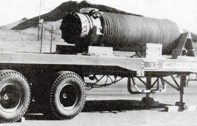
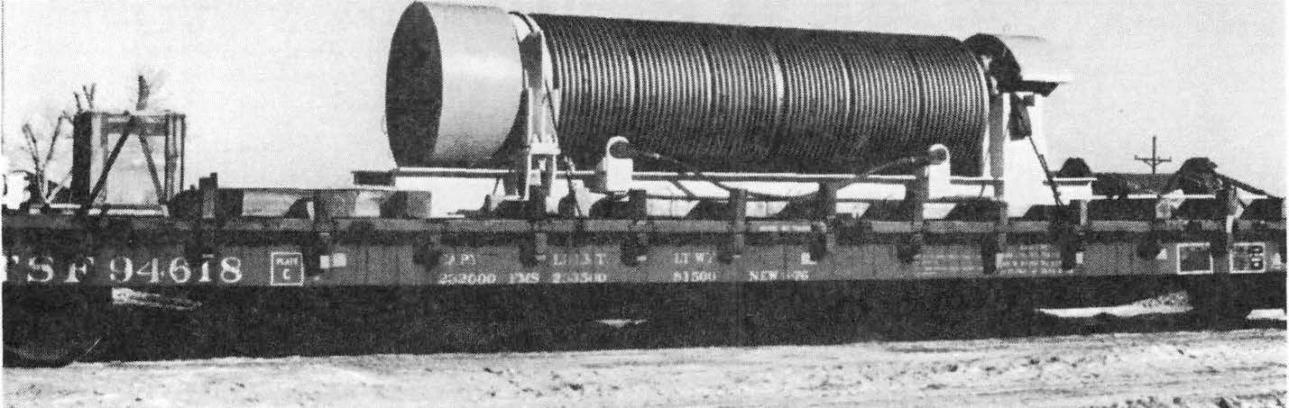
Over-the-road truck tests on superimposed shock were initially developed with cargo masses essentially from no-load to 14000 kg (30000 lb). Later, casks of 20 000 kg (44000 lb) and 25000 kg (56000 lb) were used. An image of the 11 m (35 foot) tandem axle trailer [7] for the 20 000 kg cask is shown in Figure 4. Superimposed shock tests in rail cars were developed with a cask of 45000 kg (100000 lb), Figure 5, along a typical route of 160 km (100 miles).
Initially, railcar coupling tests used light casks of 4.500 kg (10.000 lb) at impact velocities in the interval 1.23–4.99 m/s (2.76–11.2 mile/h). Afterward, these tests used casks of 36.000 kg (80.000 lb), and 63 500kg (140.000 lb). However, speeds over 3.58 m/s (8.00 mile/h) are no longer allowed in US and Canadian railway yards [8]. Since the kinetic energy of a rail car and its load are proportional to the square of its speed, coupling shock accelerations are now lower. This fact has been shown in current tests [9, 10].
Data yielded from test projects developed during the period 1960/1982 has been the main source of information for scientific research and engineering applications on shock and vibration environments for land transport for 35 years.
However, technical progress never stops. New nuclear fuel casks are bigger and weightier, heavy transportation means have evolved in both land and sea, measurement instruments are smaller, stronger, need less energy and are more precise. Last, but not least, GPS systems allow an unprecedented link between measurements taken and the locations where they happened in real-time.
Accordingly, the same question has been posed once more: Can current nuclear casks withstand the shocks and vibrations experienced during normal conditions of transport? This recurrent question was the motivation for the multi-modal transportation [9, 10, 11] test conducted in the period June-October of 2017. In this project, the US Department of Energy (DOE)—through Sandia National Laboratories and Pacific Northwest National Laboratory— collaborated with Equipos Nucleares SA, SME (ENSA), Empresa Nacional de Residuos Radiactivos S.A. (ENRESA), and ENUSA Industrias Avanzadas, SA SME (ENUSA) of Spain, and Korea Radioactive Waste Agency (KORAD), Korea Atomic Energy Research Institute (KAERI), and Korea Electric Power Corporation Nuclear Fuel (KEPCO NF).
The ENSA UNIVERSAL (ENUN) 32P 120.000 kg (264.000 lb) dual-purpose rail cask was the test load. The accelerations and strains were measured during:
1. On-travel heavy-haul truck, ship, and rail transport; 2. Handling operations between these means; 3. Controlled rail tests at the Transportation Technology Center, Inc. (TTCI), a railroad testing and training facility in Pueblo, Colorado.
During the multi-modal test, 40 accelerometers, 37 strain gauges, and three Global Positioning System channels were used to collect 6 terabytes of data over the 54- day, 7-country, 12-state, and 13.700km (8.500 miles) of travel.
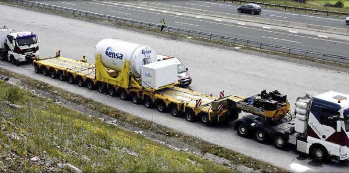
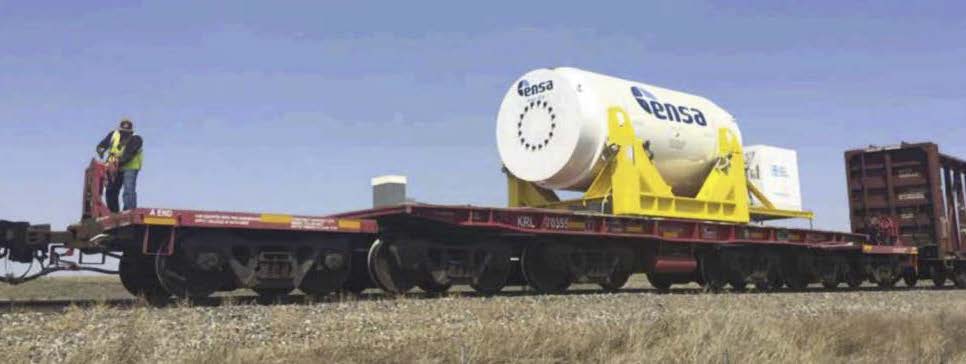
The greatest strains and accelerations were observed during the testing at TTCI, specifically during the coupling tests. Water transport strains and accelerations were the lowest. Truck heavy haul, Figure 6, and rail transport, Figure 7, strains, and accelerations were comparable. The handling tests were somewhat higher than the most extreme rail tests, except coupling. The observed strains were—in all cases— well below the yield points for nuclear fuel cladding.
The dedicated rail transport covers a 3.140 km (1.950 miles) route from the Port of Baltimore, Maryland, to Pueblo, Colorado. The trip, code-named Rail 1, took approximately six days, during which the train was moving 59 hours. A total of 2.939 shock events were identified along the rail route.
The major events of Rail 1 trip were related to tracking switches (629 events) and grade crossings (1.029 events). Only one coupling event was observed on the route from Baltimore to Pueblo, Colorado.
As previously noted, the return rail shipment—code-named Rail 2—was a non-dedicated train. Due to battery exhaustion, data collection stopped after18 days near East St. Louis, Illinois, yielding a 1.800 km (1.125 mile) test route. This route provided a valuable opportunity for considering coupling events since 30 of them were identified and analyzed.
The new multi-modal test has enhanced and clarified many previous truck and rail data and extended their scope to heavier casks. In every case, this ABS Technical Report will take into account the new data as far as they are available, jointly with the old reliable data, in order to apply the best applicable data at hand to evaluate the vibration and shock environments for the main shaft assembly transportation by truck and train in the United States. This Report data selection is shown in the following three Sections of this Chapter.
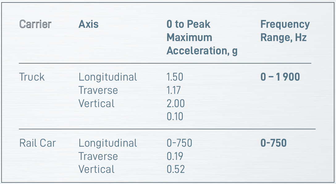
Truck and Rail Car Vibration
According to [2, 6], vibration data for truck and rail cars shows the highest levels given in Table 1. These long-established values are not contradicted by later tests. It is quite clear that vibration acceleration levels in trucks are higher than in rail cars, reaching the top values for this phenomenon in the vertical axis.
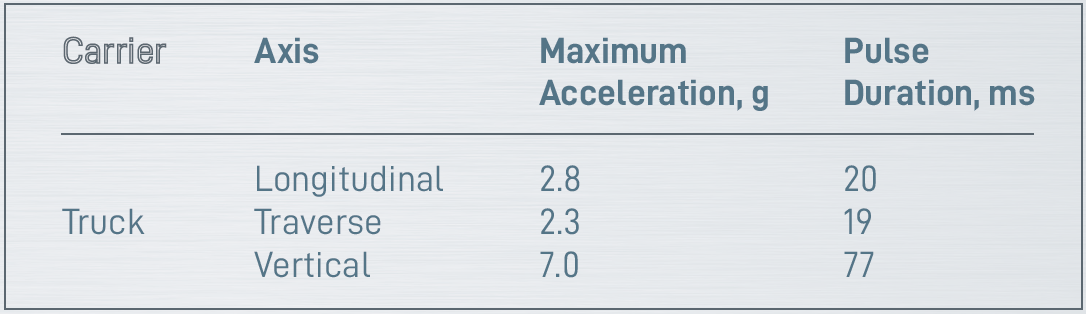
Truck Superimposed Shocks
According to [2], superimposed shock data for trucks shows the highest levels given in Table 2. Cargo weights were from zero to 14.000 kg (30.000 lb), and spring and suspension systems, were moved at speeds up to 88 km/h (55 mile/h) on a road trip from Mercury, Nevada, to Albuquerque, New Mexico. These values are compatible with earlier [2] or later [11] test data.
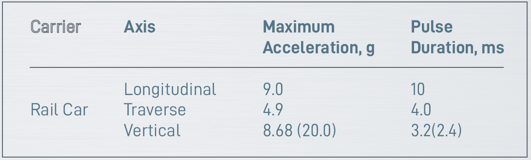
Rail Car Superimposed Shocks
According to [6], cargo weight was a 45.000 kg (100.000 lb)cask, installed on a 21 m (68 foot) flat car, with a 38 cm (15 in) end of car coupling device. Travel speeds were up to 80 km/h (50 mile/h) on a trip from Denver, Colorado, to Socorro, New Mexico. Superimposed shock data for this rail car shows the highest levels given in Table 3. These values are not contradicted by earlier tests [2]. Nevertheless, the maximum vertical acceleration of 20.0 g from [6] seems to be an extraordinary exception to be taken into account. Recent test [11] data recorded during the much longer Rail 1 trip show a sole absolute maximum peak acceleration of 8.68 g over a diamond-crossing in Jacksonville, Illinois, which seems to be a value compatible with other axes’ results. The statistics of Rail 1 superimposed shock events show that the probability of a vertical acceleration value over 3.71 g is less than 5 %.
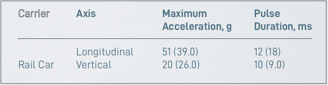
Main Shaft Assembly Shock Strength
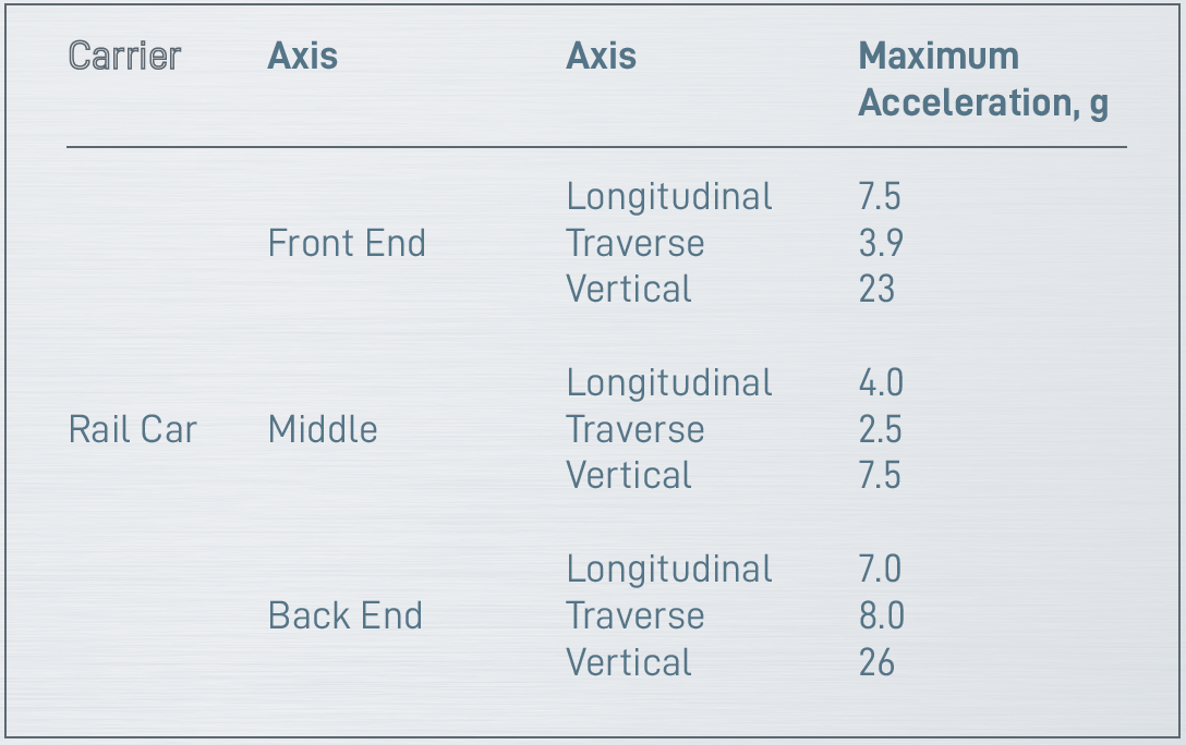
Obviously, rail car coupling shocks are the main loads on the roller bearing of the Main Shaft Assembly. Specifically, the highest values of acceleration happened in the back end of the rail car platform, Table 6. Traverse and vertical accelerations are vectorially added to become the radial acceleration, as follows.
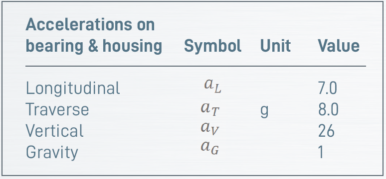
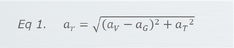
These accelerations can be vectorially added to obtain the radial acceleration applied to the main shaft bearing and housing, Equation 1.
On the other hand, the longitudinal acceleration becomes the axial acceleration applied to the main shaft bearing, Equation 2.

The masses of the bearing and its housing are given in Table 7.
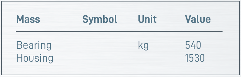
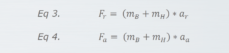
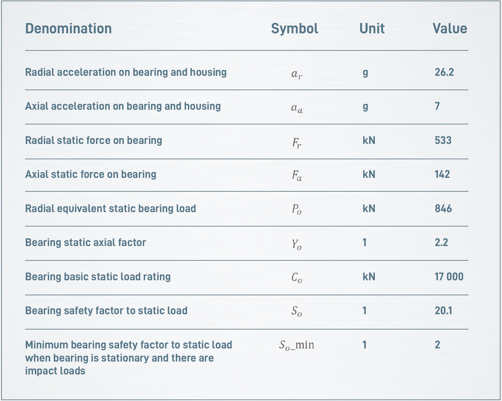
The maximum radial and axial forces acting on the bearing are, according to Equation 3 and Equation 4,
The radial equivalent static bearing load, according to Equation 5, is:

Where Yo is the bearing static axial factor.
The safety factor of the bearing to static load is, according to Equation 6, is:

The results of the calculation of the bearing strength to the rail car coupling shock loads are shown in Table 8.
Results of the calculation of the bearing strength
Conclusions
The current article has posed the following problem: Is it safe to send the main shaft assembly normally packed by train, without suffering damage due to the vibration and shock environment of standard rail cars? This article has shown that the answer to this problem is YES. Truck and railcar vibration and shock environments are compared through the corresponding accelerations. It is shown that vibration and superimposed shocks of train travel are comparable to those of trucks, and the only difference relies on the coupling shocks of rail cars, which may reach higher values during the process of train formation. It is shown in the report that coupling shocks of standard current US trains are aptly supported by the main shaft assembly bearing, with a safety factor of 20, well above the recommended minimum of 2, for the caseload at hand.
References
1. [1] J. T. Foley and M. B. Gens, Shock and Vibration Measurements During Normal Railroad and Truck Transport, Albuquerque, New Mexico: Sandia Laboratories, 1971.
2. [2] C. F. Magnuson and L. T. Wilson, Shock and Vibration Environments for Karge Shipping Containers on Rail Cars and Trucks SAND76-0427 (NUREG766510), Albuquerque, New Mexico: Sandia Laboratories, 1977.
3. [3] C. F. Magnuson, Shock and Vibration Environments for Large Shipping Container During Truck Transport (Part I) SAND77- 1110, Albuquerque, New Mexico: Sandia National Laboratories, 1977.
4. [4] C. F. Magnuson, Shock and Vibration Environments for Large Shipping Container During Truck Transport (Part II) SAND78- 0337, Albuquerque, Nerw Mexico: Sandia National Laboratories, 1978.
5. [5] C. F. Magnuson, Shock Environments for Large Shipping Containers During Rail Coupling Operations SAND79-2168 (NUREG/ CR-1277), Albuquerque, New Mexico: Sandia National Laboratories, 1980.
6. [6] C. F. Magnuson, Shock and Vibration Environments Encountered During Normal Rail Transportation of Heavy Cargo SAND82-0819, Albuquerque, New Mexico: Sandia National Laboratories, 1982.
7. [7] G. H. Lamoreaux, A. A. Trujillo and C. Magnuson, Truck and Rail Shock and Vibration Environments During Normal Transport, Albuquerque, New Mexico: Sandia National Laboratories, 1982.
8. [8] D. B. Loftis, Coupling Speed Regulation: Coupling Speeds ->Damage Study, Clayton, Missouri: Olin Corporation, 2017.
9. [9] E. Kalinina, C. Wright, N. Gordon and S. Saltzstein, Cask Transportation Project — Preliminary Results SAND2018-4423C, Albuquerque, New Mexico: Sandia National Laboratories, 2018.
10. [10] E. Kalinina, C. Wright, L. Lujan and S. Saltzstein, Shock Environments for the Nuclear Fuel Transportation System SAND2019-6806 C, Albuquerque, New Mexico: Sandia National Laboratories, 2019.
11. [11] E. A. Kalinina and et al., International Multi-Modal Spent Nuclear fuel Transportation Test: The Transportation Test Triathlon SAND2019-1995C, Albuquerque, New Mexico: Sandia National Laboratories, 2019.
José Martínez-Escanaverino
 ABS Group Scientific Director.
IEEE Senior Membership
AGMA Technical Committee Member.
Author of “Calculation Methods for Wear and Tear of Engineering Chains”.
Creator of the “Engineering Problem Solving System” (In the process of getting a patent).
For decades, Dr. Escanaverino has blended engineering education with practical engineering work. His main industrial projects involve actuators, drives and solving computational problems. His experience has proven to have a transcendental impact for universities, project centers and plants in Cuba —his country of origin— and Venezuela, Brazil, Netherlands, Germany, Switzerland, Mexico and the United States. Since his full incorporation into the ABS team at the end of 2014, the author has participated in more than 600 engineering projects.